
How to draw a state machine diagram
Draw a state machine diagram in UML: states, transitions, guards and entry actions, with a document review example you can check against a simple table.
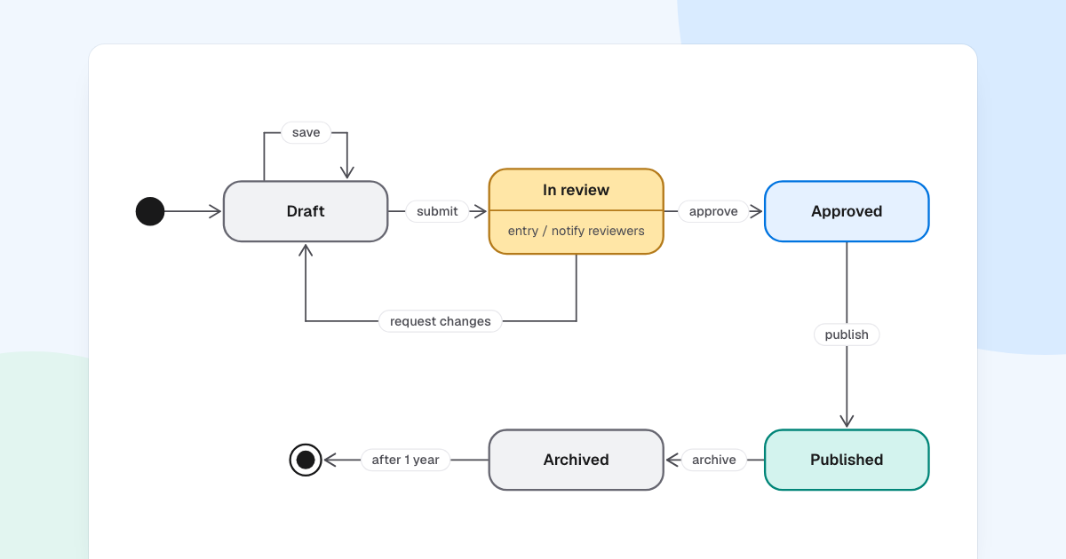
What should happen if someone clicks publish on a document still in review? If your team cannot answer quickly, the rules are living in people’s heads. When you draw a state machine diagram, they end up on a page where anyone can check them.
Quick AnswerA state machine diagram shows the states an object can be in and the events that move it between them. To draw one, list the states, mark the start and the end, then add an arrow for every allowed change, labeled with the event that causes it.
What is a state machine diagram?
Also called a statechart or state diagram, it is a UML behavior diagram about one object and its life: an order, a ticket, a document.
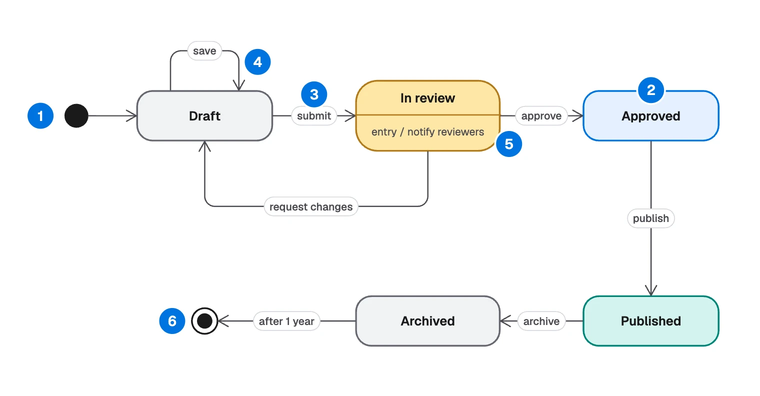
- Initial state: a filled circle, where the object starts.
- State: a rounded rectangle, a condition that lasts.
- Transition: an arrow with a label, an allowed move.
- Self-transition: an arrow back to the same state. It leaves the state and enters it again.
- Internal activity:
entry /,do /orexit /inside the state, for work on arrival, during the stay or on leaving. - Final state: a filled circle in a ring, where its life ends.
It is the right tool when the same action means different things at different times. Clicking cancel on an unpaid order and on a shipped one should do different things.
State or step?
Most bad state machines are flowcharts in disguise, so get this right first.
| Flowchart | State machine | |
|---|---|---|
| A box means | An action being done | A condition that lasts |
| An arrow means | Then do this | This event moves it |
| It follows | A process | One object |
| It answers | What happens next? | What is allowed now? |
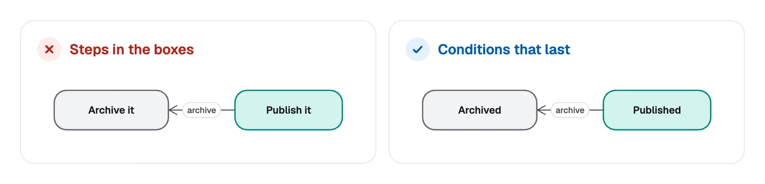
To test a name, try “the document is ___”. “In review” and “Published” work. “Send for review” and “Publish it” do not: they are steps, and belong on an arrow or in a flowchart.
State machine diagram notation
Beyond the parts above, three symbols cover most other needs:
| Element | Looks like | Means |
|---|---|---|
| Choice | Small diamond | One arrow in, several guarded arrows out |
| Composite state | A state holding other states | Inner states share its transitions |
| History | Circled H | Return to the inner state you last left |
A full transition label has three parts, all optional: trigger [guard] / effect. So approve [reviewer is not author] / notify author means: on approve, if the reviewer is someone else, move on and notify the author.
Many real diagrams need only the trigger. The UML specification has the formal rules.
The document workflow, as a table
You can check any state machine by rewriting it as a table:
| State | Event | Next state |
|---|---|---|
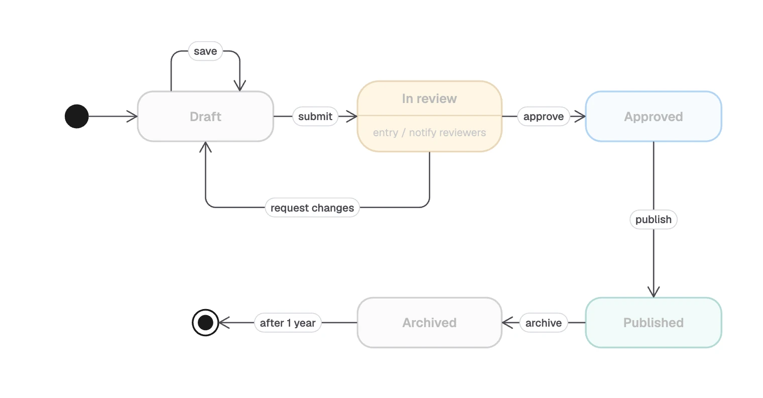
| Draft | save | Draft |
| Draft | submit | In review |
| In review | approve | Approved |
| In review | request changes | Draft |
| Approved | publish | Published |
| Published | archive | Archived |
| Archived | after 1 year | Final state |
Start with the question from the top of this guide:
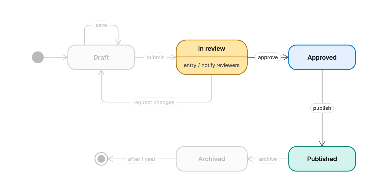
- The missing arrow is the rule. Nothing leaves “In review” on publish, so that click does nothing. In UML, an event with no matching transition is discarded unless the state defers it.
- “save” is a self-transition, so any entry or exit action would run each time.
- “entry / notify reviewers” sits inside “In review”. It runs on every arrival, so no incoming arrow has to repeat it.
- “request changes” goes backward. Loops are normal.
- “after 1 year” is a time event. Nobody clicks it. The passing of time triggers it.
How to draw a state machine diagram
Pick one object
“A document”, not “the publishing system”. Two objects need two diagrams, and a sequence diagram can show how they talk.
List its states
A status column in your database is a good start. Test each name with “the document is ___“.
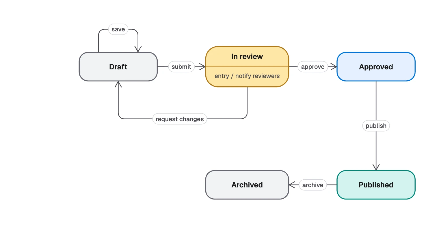
States first, with nothing joining them Mark the start and the end
Some objects never finish, and those need no final state.
Ask of each state what can happen here
Add an arrow for every event that changes something.
Then the start, the end and each allowed move Add guards and effects only where they change the meaning
Keep guards on the same event from overlapping.
Check it
Every state should be reachable from the start, and only final states should lack a way out. Walk through the table with someone who knows the rules.
Collapse repeats
If “cancel” leaves five states, wrap them in a composite state and draw one arrow.
State machine diagrams in FlowDraw
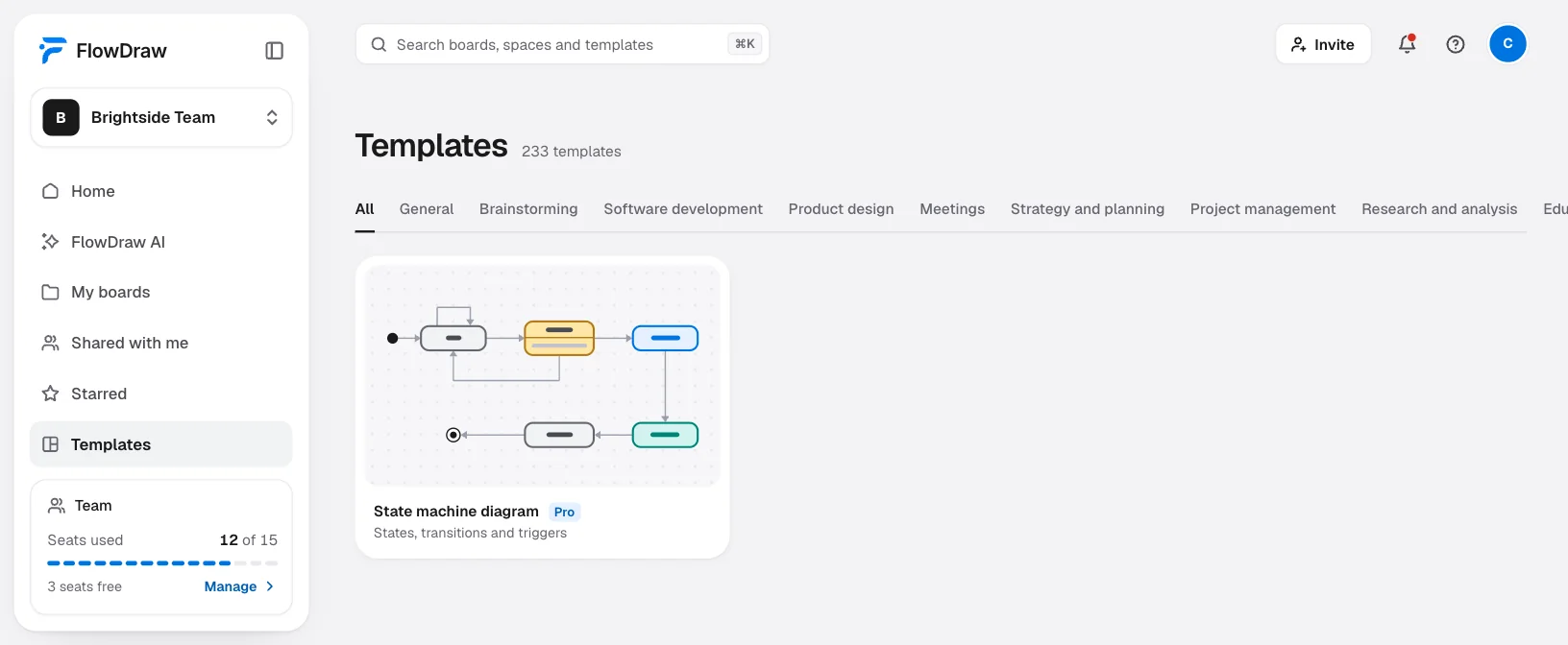
The “State machine diagram” template and the UML library come with Pro or Team. On Free the preview offers “Upgrade” in place of “Use template”.
Open the template
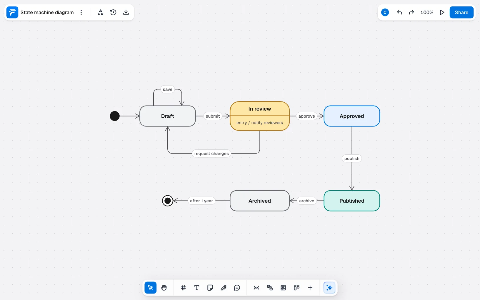
Search for “State machine diagram” under “Templates”, open the preview and click “Use template”. “Order state machine” is a second worked example, also on Pro. To start blank, open a “Blank board”, then the “State machine” group in the UML section of “Shape library”.
Rename the states
Select a state and type. The group also has “Composite state”, “Initial state”, “Final state”, “Choice” and “History”: click a cell and then the board.
Draw the transitions
Pick the “Transition” cell and draw between two states. Type the event in “Add a label”. For a self-transition such as “save”, draw from a dot on one side out to empty board, then drag the loose end to a dot on another side.
Keep a state’s text together
In the template, the name and the “entry” line of “In review” are separate text boxes on top of the state. Select all three and press ⌘G (Ctrl+G on Windows).
Review the rules
Click “Share” and invite the people who know the rules with “Can comment”. “Export” gives you PNG, SVG or PDF for the spec.
On Free, the same notation is possible with free shapes:
- States: “Rounded rectangle” from “Basic shapes”, with entry actions on a second line of the text.
- Initial state: a “Circle” with a dark fill from “More fill colors”.
- Final state: a small dark circle inside a larger ring.
- Transitions: with nothing selected, press L and set the end to “Open arrow”.
State machine mistakes that cause bugs
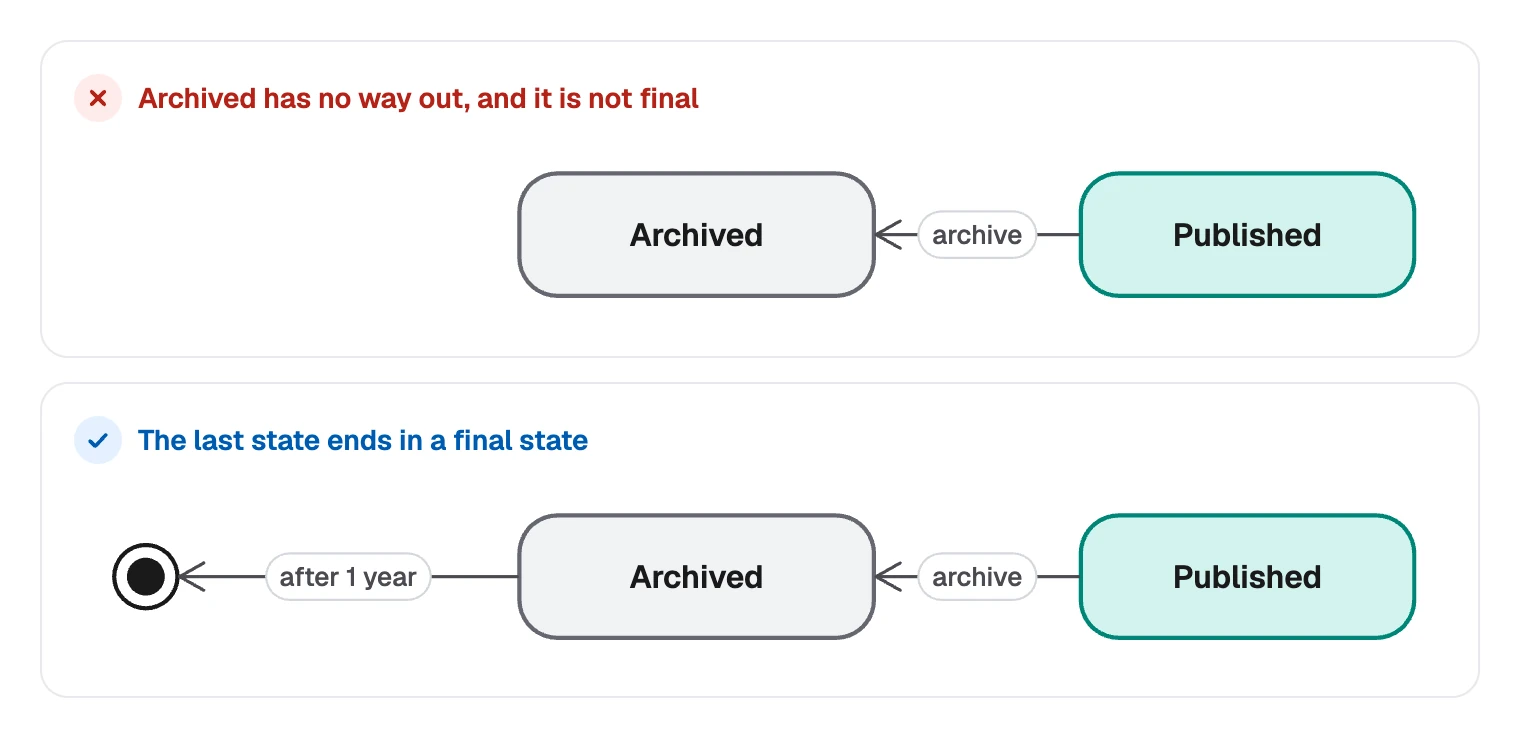
Dead ends are the easiest to miss. A state with no way out that is not final usually means a forgotten rule, and it often shows up later as a stuck record.
- Actions named as states. “Send email” is something that happens on the way, not a place the object can sit.
- Arrows with no event. In UML, an unlabeled transition fires as soon as the state’s work is finished. Most people mean something else, so name the event.
- Overlapping guards.
[total >= 100]and[total <= 100]both pass at exactly 100. Neither the diagram nor the code can say what happens then. - Two objects on one diagram. A document’s states and its reviewer’s states change for different reasons. Keep them apart.
When you have a status column you do not fully trust, create an account and start by listing its values.
FAQ
A flowchart shows actions in order: do this, then that. A state machine diagram shows the conditions one object can be in and the events that move it between them.