
How to draw a use case diagram
Draw a use case diagram with actors, use cases and a system boundary, and get include and extend the right way around, using an online store as the example.
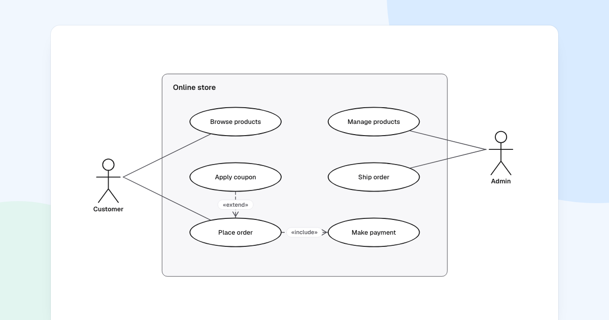
A use case diagram is a one-page answer to two questions: who uses this system, and what can they do with it? To draw a use case diagram you need only a few symbols, plus a clear head about include and extend.
Quick AnswerA use case diagram shows what a system does for the people and systems around it. To draw one, draw a box for the system, put actors outside it and use cases inside it as ovals named with a verb and a noun, then connect each actor to its goals.
What is a use case diagram?
It is a UML behavior diagram drawn from the outside looking in. It leaves out screens, steps and data on purpose.
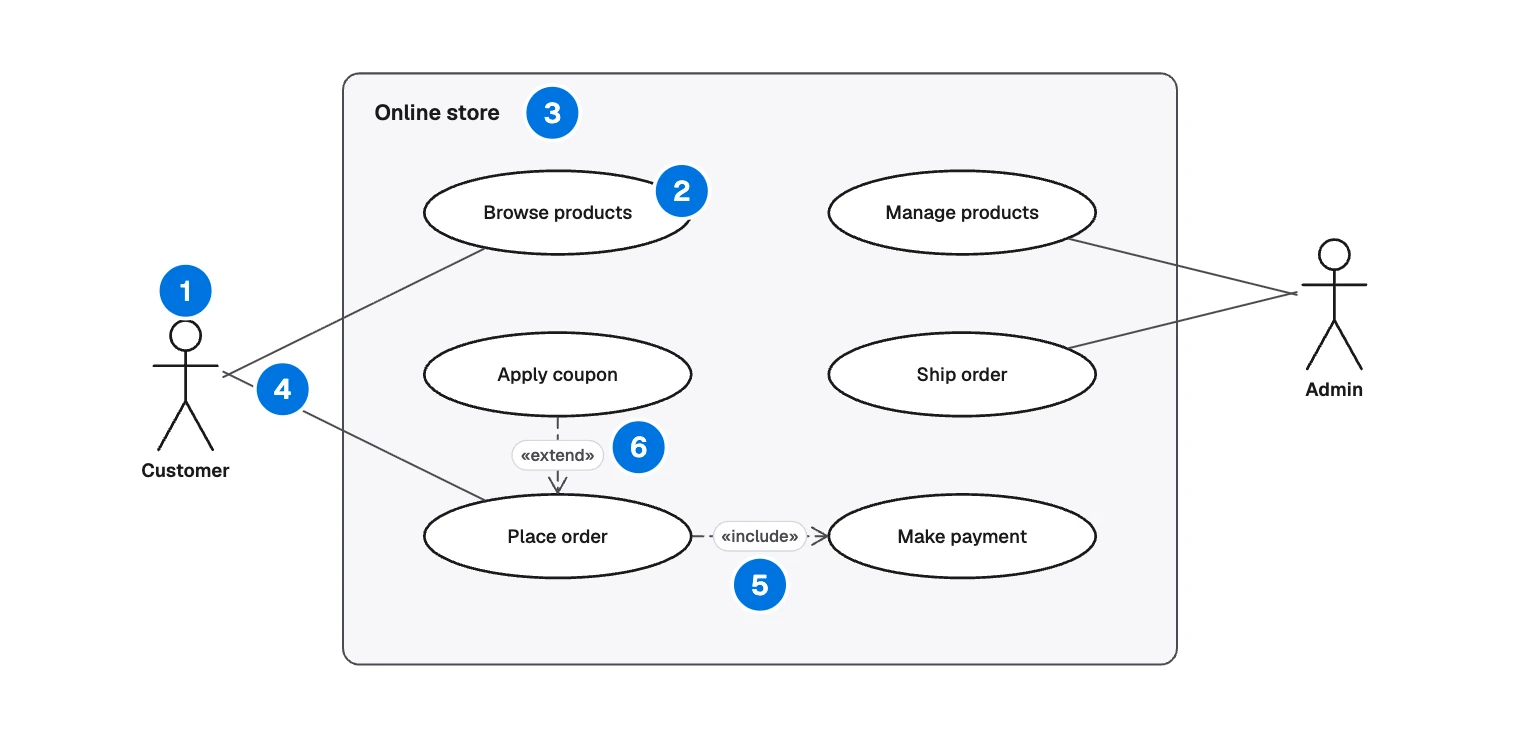
That makes it useful early: agreeing scope with a client, splitting a product into features, or checking that nobody has been forgotten.
It stops helping when the question becomes “how”:
- For steps, draw a flowchart.
- For messages between parts of the system, draw a sequence diagram.
- For the main flow and the exceptions, write a description of each use case. The diagram does not replace it.
Use case diagram symbols
The numbers match the pins above.
| # | Symbol | Looks like | Means |
|---|---|---|---|
| 1 | Actor | Stick figure outside the box | A role or outside system with a goal |
| 2 | Use case | Oval, named verb and noun | A goal the system fulfills |
| 3 | System boundary | Box with a name | What is in scope |
| 4 | Association | Solid line | This actor takes part |
| 5 | Include | Dashed arrow marked «include» | The base always does this |
| 6 | Extend | Dashed arrow marked «extend» | An optional addition to the base |
| - | Generalization | Solid line, hollow triangle | A special kind of actor or use case |
The example has no generalization.
Include or extend?
This is the part people argue about. Ask one question: can the base use case finish without it?
- No, it always happens: include. Nobody places an order without paying, so “Place order” includes “Make payment”. The arrow points from the base to the included use case.
- Yes, only sometimes: extend. An order works fine with no coupon, so “Apply coupon” extends “Place order”. The arrow points from the extension to the base.
The arrows look backward until you read them as sentences. If your sentence is false, your arrow is the wrong way around.
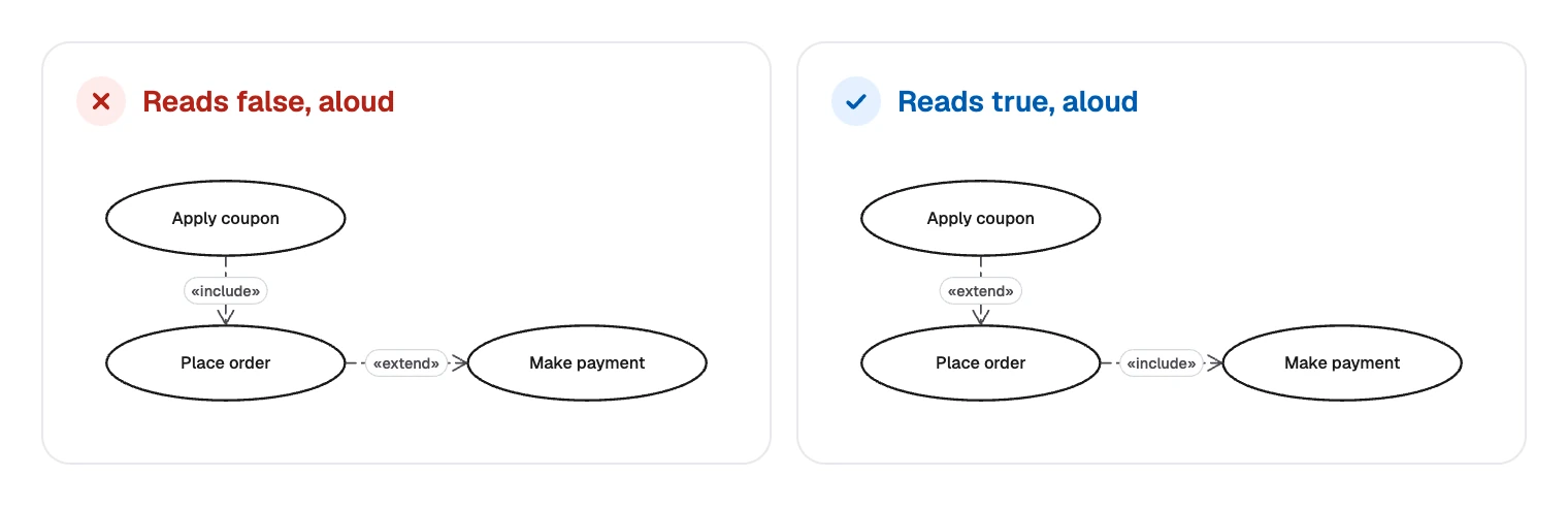
Use both sparingly. Include pays off when two or more use cases share a piece of behavior. Extend pays off when an optional part has rules worth naming.
Reading the online store
- Actors stay outside the box. “Customer” is on the left and “Admin” on the right, a common habit that keeps the main user first.
- Each actor reaches only its own goals. “Customer” connects to “Browse products” and “Place order”. “Admin” connects to “Manage products” and “Ship order”.
- “Make payment” and “Apply coupon” have no actor line. They happen inside “Place order”. If the payment provider mattered, you would add it as an actor joined to “Make payment”.
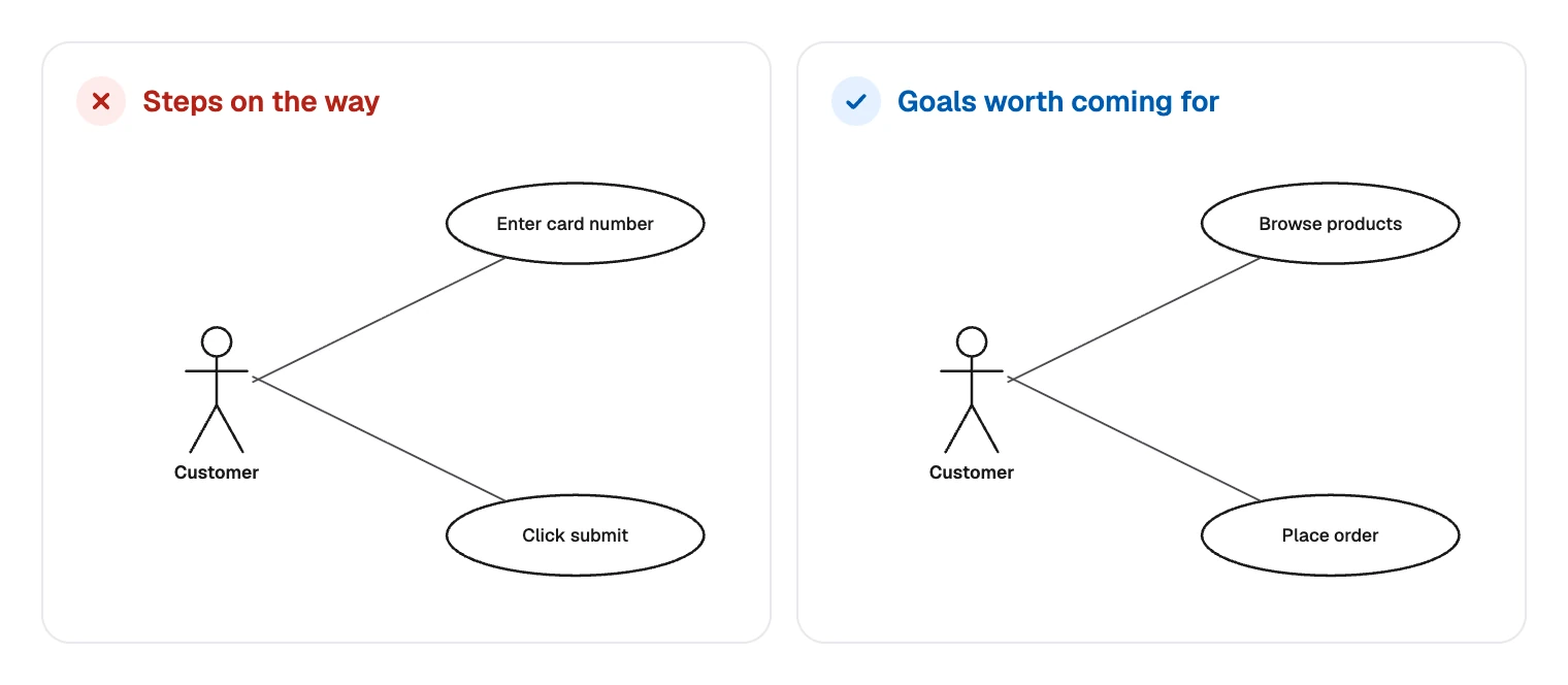
- There is no “Log in”. It is a step on the way to a goal. Nobody comes to a store in order to log in.
How to draw a use case diagram
Draw the boundary and find the actors
Deciding what sits inside is half the value of the exercise. Ask who uses it, who runs it, and which other systems send or receive something. Name roles, not people.
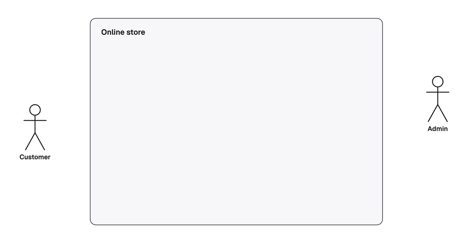
The boundary and who stands outside it List each actor’s goals
Ask what this actor comes here to do, and write a verb and a noun. A use case is complete when the actor could walk away satisfied.
Connect actors to goals
Use plain lines. No arrowheads are needed.
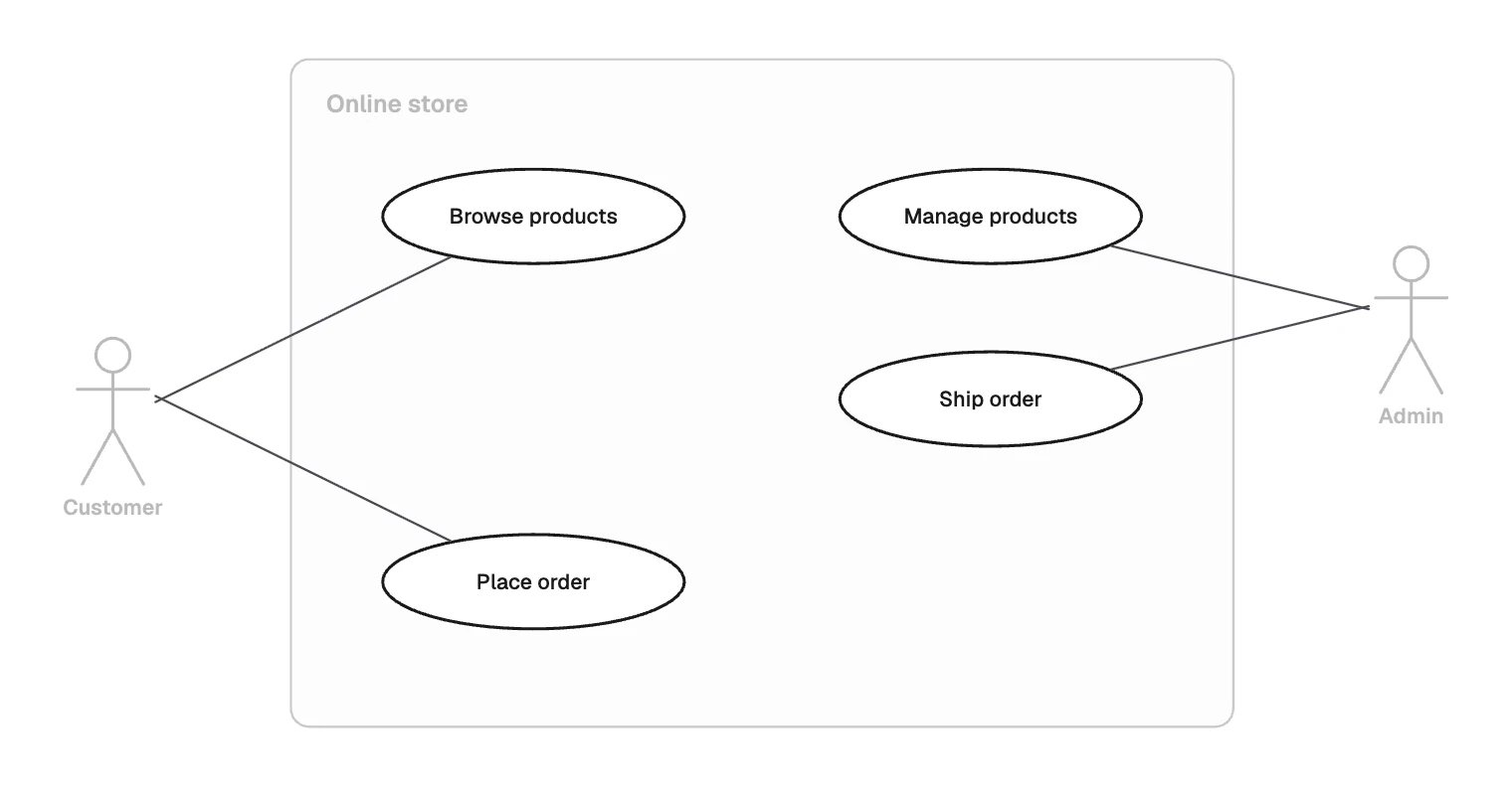
Each actor joined to its own goals Pull out include and extend
Do it only where it makes the diagram clearer.
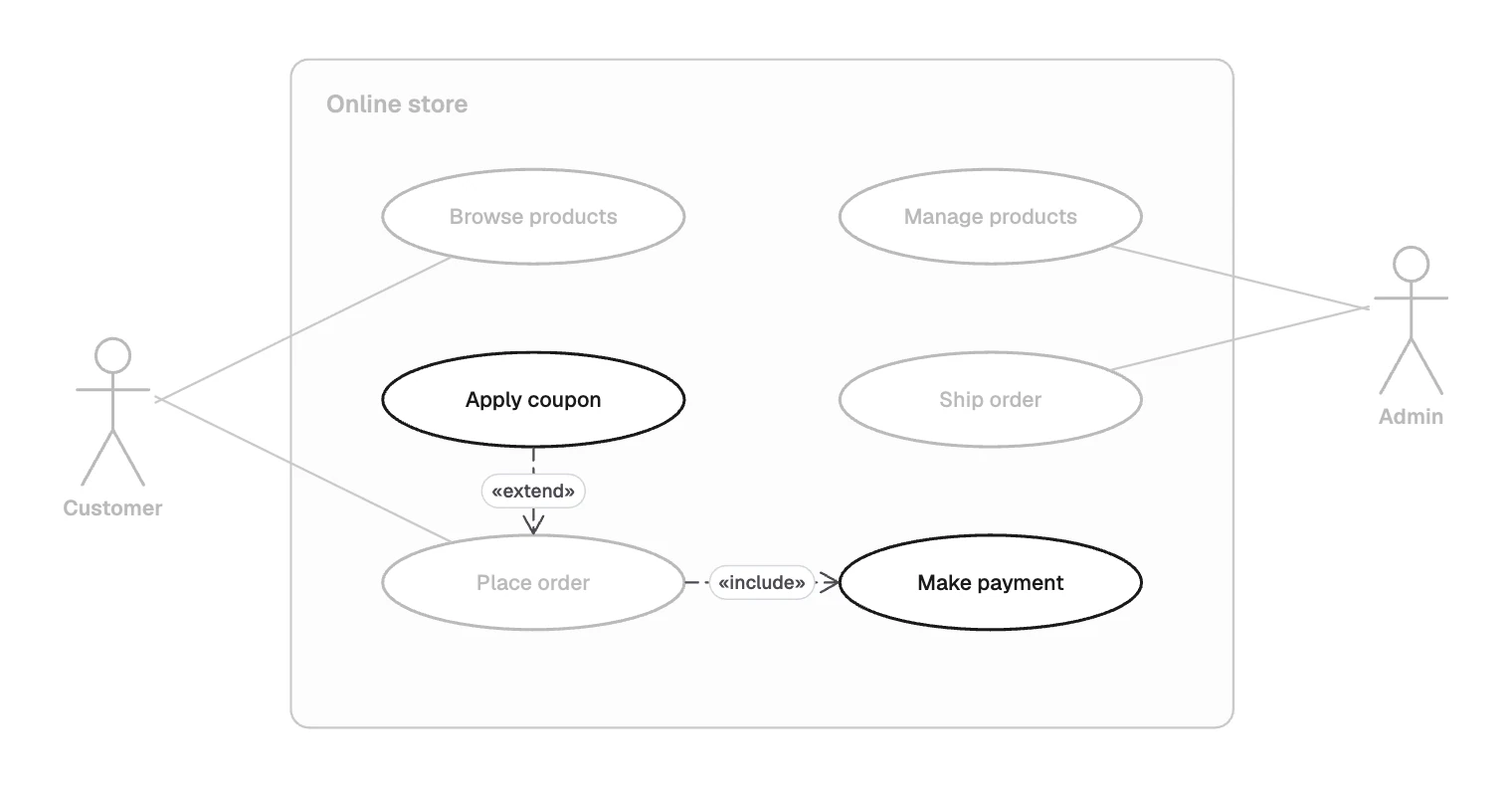
Shared or optional parts come last Check the edges
Every actor needs at least one use case, and every use case needs a line to an actor or another use case.
Draw a use case diagram in FlowDraw
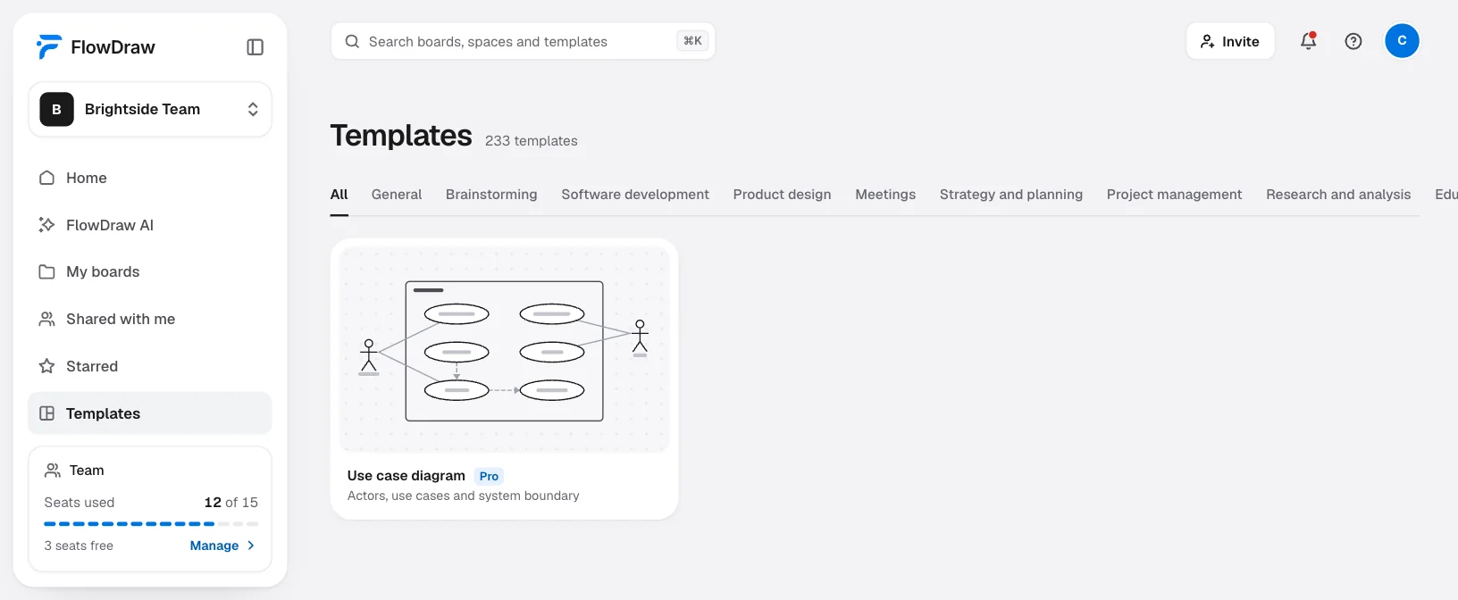
The “Use case diagram” template and the UML library come with Pro or Team. On Free the template’s preview offers “Upgrade” in place of “Use template”.
Open the template
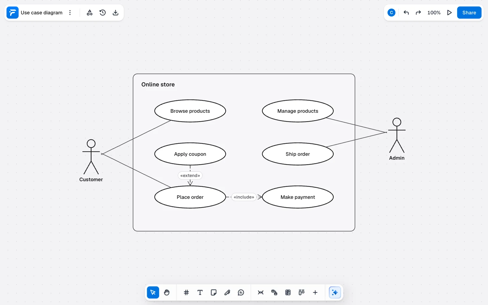
Search for “Use case diagram” under “Templates”, open the preview and click “Use template”. To start blank, open a “Blank board”, then the “Use case” group in the UML section of “Shape library”.
Change the goals
Select an oval and type. Do the same for each actor’s name.
Add shapes
The “Use case” group has “Actor”, “Use case” and “System boundary”. Click a cell and then the board, or drag it across.
Draw the lines
Pick “Association”, “Include” or “Extend” in the library, then draw from one shape to the other. “Include” and “Extend” already carry their labels. If an arrow lands at the wrong end, use “Swap ends” in “Line properties”.
Settle the scope
Click “Share” and invite people with “Can comment”. A comment pinned to an oval is a good place for “is this in scope?“. “Export” gives you a PNG or PDF for the spec.
Drawing one on Free
The notation does not depend on special shapes, so free tools can draw all of it:
- System boundary: with nothing selected, press F and drag out a frame, then double-click its title to name it. Anything lying wholly inside moves with the frame.
- Use cases: “Ellipse” from “Basic shapes”, or press O.
- Actors: a labeled “Rectangle”, since UML also allows a rectangle marked «actor» above the name. The Pen tool can draw a figure in a few strokes.
- Lines: press L with nothing selected, and set the end to “None”.
- Include and extend: choose “Dashed” and the “Open arrow” end, then type «include» or «extend» in “Add a label”.
Use case diagram mistakes
The first one is the most common: steps dressed up as use cases. If the actor would not stop there and call it done, it is not a use case.
- Include and extend the wrong way around. Read the arrow aloud as a sentence.
- Ovals in a chain. Arrows that show “first this, then that” turn it into a bad flowchart.
- Actors inside the boundary. If it is part of the system, it is not an actor.
- Job titles or names as actors. One person can be both a customer and an admin. The actor is the role they are playing at that moment.
- Dozens of ovals. Split by actor or by feature area, with one diagram for each.
Have a system in mind? Start with a free account and sketch its boundary before anything else.
FAQ
Include means the base use case always performs the other one, so the arrow points from the base to the included use case. Extend means the other use case is optional and adds to the base under some condition, so the arrow points from the extension to the base.